Class diagrams are the main building blocks of object-oriented modeling so it is important that you understand the various class diagram relationships and how they affect your solution. We have listed them below with examples.
Creately simplifies creating class diagrams by showing the logical relationship based on context.
Create a class diagram >>Class Diagram Relationships
Classes are interrelated to each other in specific ways. In particular, relationships in class diagrams include different types of logical connections. The following are such types of logical connections that are possible in UML:
- Association
- Directed Association
- Reflexive Association
- Multiplicity
- Aggregation
- Composition
- Inheritance/Generalization
- Realization
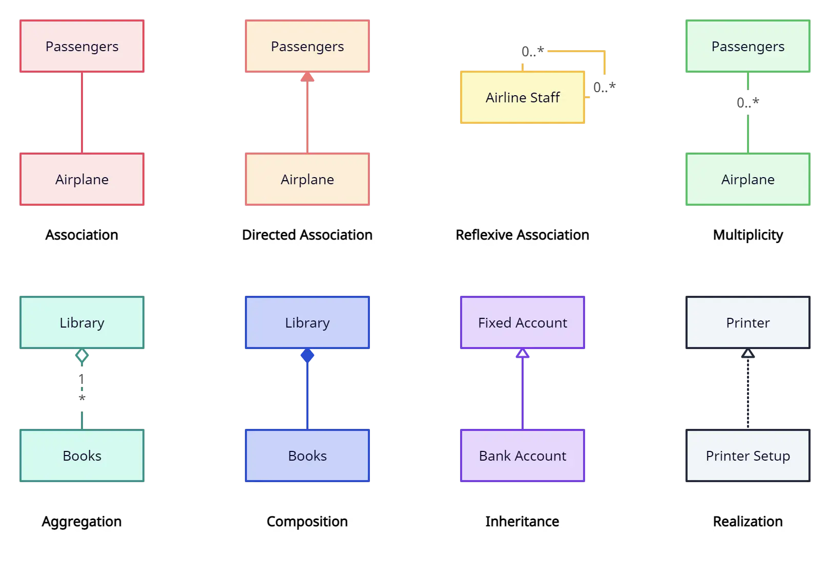
Relationships in UML Class Diagrams
Association
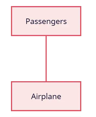
is a broad term that encompasses just about any logical connection or relationship between classes. For example, passengers and airline may be linked as above.
Directed Association
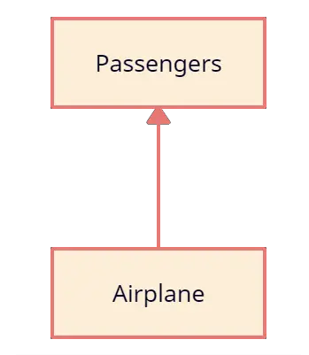
refers to a directional relationship represented by a line with an arrowhead. The arrowhead depicts a container-contained directional flow.
Reflexive Association

This occurs when a class may have multiple functions or responsibilities. For example, a staff member working in an airport may be a pilot, aviation engineer, ticket dispatcher, guard, or maintenance crew member. If the maintenance crew member is managed by the aviation engineer there could be a managed by relationship in two instances of the same class.
Multiplicity
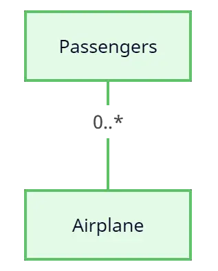
is the active logical association when the cardinality of a class in relation to another is being depicted. For example, one fleet may include multiple airplanes, while one commercial airplane may contain zero to many passengers. The notation 0..* in the diagram means “zero to many”.
Aggregation
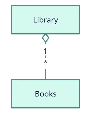
refers to the formation of a particular class as a result of one class being aggregated or built as a collection. For example, the class “library” is made up of one or more books, among other materials. In aggregation, the contained classes are not strongly dependent on the lifecycle of the container. In the same example, books will remain so even when the library is dissolved. To show aggregation in a diagram, draw a line from the parent class to the child class with a diamond shape near the parent class.
To show aggregation in a diagram, draw a line from the parent class to the child class with a diamond shape near the parent class.
Composition
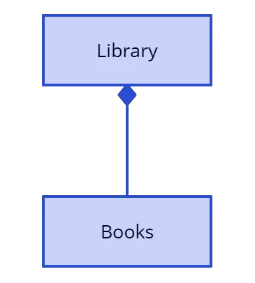
The composition relationship is very similar to the aggregation relationship. with the only difference being its key purpose of emphasizing the dependence of the contained class to the life cycle of the container class. That is, the contained class will be obliterated when the container class is destroyed. For example, a shoulder bag’s side pocket will also cease to exist once the shoulder bag is destroyed.
To show a composition relationship in a UML diagram, use a directional line connecting the two classes, with a filled diamond shape adjacent to the container class and the directional arrow to the contained class.
Inheritance/Generalization
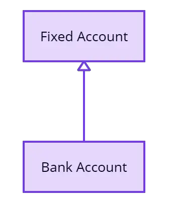
refers to a type of relationship wherein one associated class is a child of another by virtue of assuming the same functionalities of the parent class. In other words, the child class is a specific type of the parent class. To show inheritance in a UML diagram, a solid line from the child class to the parent class is drawn using an unfilled arrowhead.
Realization
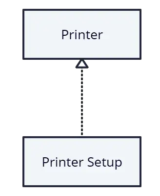
denotes the implementation of the functionality defined in one class by another class. To show the relationship in UML, a broken line with an unfilled solid arrowhead is drawn from the class that defines the functionality of the class that implements the function. In the example, the printing preferences that are set using the printer setup interface are being implemented by the printer.
Drawing class diagrams using Creately
We’ve given a lot of thought to relationships when we built our class diagramming tools. Our connectors adjust to the context and show only the most logical relationships when connecting classes. This significantly reduced your chances of making a mistake.
Create a class diagramDrawing from scratch can be cumbersome. You can get started immediately using our professionally designed class diagrams. Browse our class diagram examples and pick the one that’s closely related to your system.
What are the Class Diagrams?
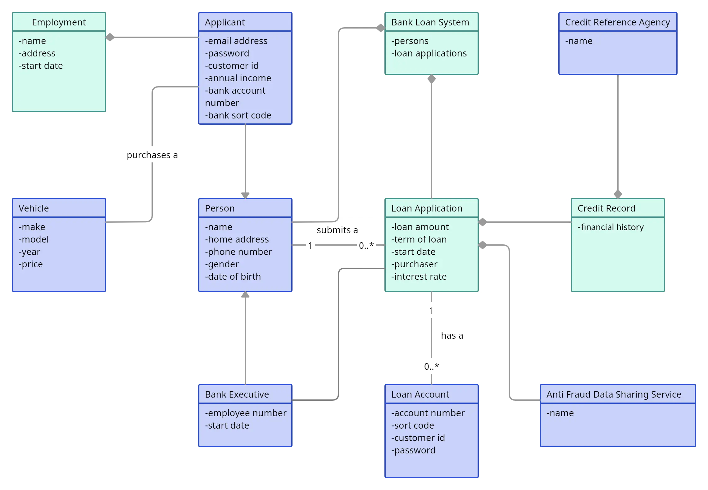
Class diagrams are the main building block in object-oriented modeling. They are used to show the different objects in a system, their attributes, their operations, and the relationships among them.
The following figure is an example of a simple class:
In the example, a class called “loan account” is depicted. Classes in class diagrams are represented by boxes that are partitioned into three:
- The top partition contains the name of the class.
- The middle part contains the class’s attributes.
- The bottom partition shows the possible operations that are associated with the class.
The example shows how a class can encapsulate all the relevant data of a particular object in a very systematic and clear way. A class diagram is a collection of classes similar to the one above.
Any More Questions About Class Diagram Relationships?
I hope I’ve clearly explained the various relationships between class diagrams. They are not as complex as you think and can be mastered with some practice. And by using our tool you shouldn’t have any trouble coming up with class diagrams. If you have any more questions don’t hesitate to ask in the comments section. Also, check out this guide to UML Diagram Types with Examples for further reading.
References:
1. An introduction to structure diagrams in UML 2 by Donald Bell
2. Class diagram as published on the Wikipedia website
3. The UML Class Diagram Part 1 as published on the website developer.com
4. The Class Diagram from Visual Case Tool – UML Tutorial as published on Visual Case website
5. Associations as published on the Sybase website


